Installing OpenWRT onto Linksys E5400
I installed OpenWRT on a router using the TFTP method, using a Linux system as the host.
Overview
A lot of these instructions can be derived from the official OpenWRT page for the E5400 but the details were a bit sparse, so I needed to do lots of Googling on my own. This post is a compilation of information needed to complete the installation and setup. Unlike the wiki, these instructions are comprehensive and detailed on where I managed to stumble.
Step 1: Opening the router
We need a way to interact with the bootloader. We do this by opening a serial console via UART.
We first need to open the router, by tearing through the sticker and unscrewing at the locations below.
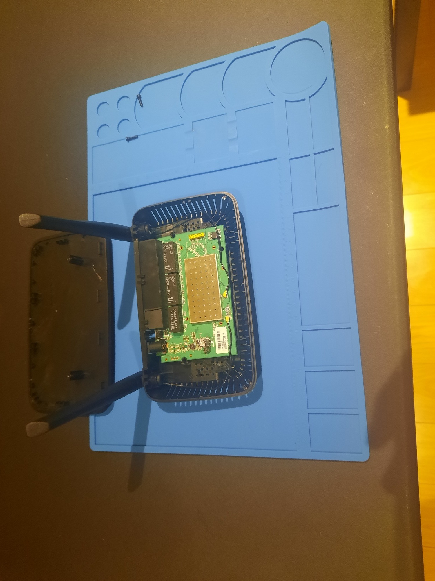
 Then, run a shim across the top lid, and attempt to slide off the cover towards the front of the router. This part was surprisingly difficult for me; I broke a few plastic bits before finally getting it off. The router should now look as below.
 Carefully remove the antenna connectors at the bottom center-left, the slide the pcb out of the case.
Step 2: Soldering pin headers
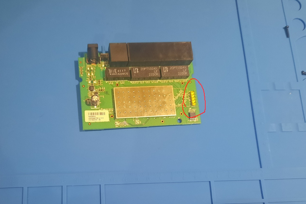
The pcb should needs to be soldered with a 5-pin breakaway header where shown. Remember to have the long parts pointing up, and the plastic bit above the pcb.
 This is great practice for someone learning to solder, so don’t let this daunt you! Now you can place the board into its case, and reattach antennae.

Step 3: UART Wiring
Warning: Doing this with an Arduino is a terrible idea! RISK OF BURNING BOARD!
According to the relevant wiki article, the router expects a 3.3v serial connection, while an Arduino Uno uses 5v logic for TTL. It didn’t burn my model, but someone following my instructions has reportedly burned out thiers. Use a proper USB-Serial connector like below, and make sure to set it to 3.3v logic by moving the yellow connector to VCC and 3V3!
 For wiring, according to the wiki page the pinout (from back to front with the router facting forwards) is
- VCC
- TX (or TXD)
- RX (or RXD)
- (Empty)
- GND
Connect these to the corrosponding pins on your USB board, remembering to swap RX(D) and TX(D).
We now need to communicate the router. To do this you will need a UART to USB adapter. While this can be bought individually, many microcontroller boards have one built in that we can abuse. Here I use an Arduino Uno, and connect the RESET pin to GND for the desired effect.
 The Uno is connected to the host system through USB. The female-to-male jumper wires are connected as shown:
 Note that although a shared ground may not be required for this case I include it just to be safe.
Step 4: Creating a Terminal
Now, we need to open a terminal with Linux. We will be using screen so you must install it if you do not already have it. It is a well known Linux package.
First we need to get the device path of our Arduino. There are many ways to do this, but here is a very simple one. First run (with Arduino unplugged)
ls /dev/ > ./before.txt
Now plug in your Arduino.
ls /dev/ > ./after.txt
diff before.txt after.txt
86d85
< serial
161d159
< ttyACM0
So our device path is /dev/ttyACM0. The path we are looking for must have ‘tty’ since we have a serial device. Remember to rm before.txt after.txt when done!
To create your terminal, run
screen /dev/ttyACM0 115200 # 115200 is the baud rate used by the router
This should clear your terminal. If the device you are using has RX and TX lights, then typing should cause one of them to light up. If you press enter while the router is on, you should have a simple terminal prompt show up.
#
Try running ls.
ls /
If you get reasonable output, success!
Step 5: Default Firmware Setup
We will use the TFTP method to install the new firmware. This works by hosting a TFTP server with our firmware image, then instructing the routers bootloader to fetch it and execute. First, restart your router (without disconnecting UART). You will get alot of bootlog text, but wait until this prompt appears:
Please choose the operation:
   1: Load system code to SDRAM via TFTP.
   2: Load system code then write to Flash via TFTP.
   3: Boot system code via Flash (default).
   4: Entr boot command line interface.
   7: Load Boot Loader code then write to Flash via Serial.
   9: Load Boot Loader code then write to Flash via TFTP.
Input a 4. Then input the following commands
setenv serverip 192.168.1.1
setenv ipaddr 192.168.1.100
setenv bootfile openwrt-ramips-mt76x8-linksys_e5400-initramfs-kernel.bin
saveenv
reset # Reboots the router
These set the default values for a later step. The IP addresses were chosen arbitrarily, though I cannot guarantee that any valid combination will work.
Step 6: TFTP Server Setup
First we install a TFTP server to our Linux machine. Since my machine uses Mint, I used this guide. However the guide contains a major inaccuracy so I will simplify it here. First
sudo apt-get install tftpd-hpa
sudo service tftpd-hpa status
If you see ‘Running’, then your TFTP server is already up (press q to exit)! Now we need to make it host our firmware file. First download it from here. Then move it to /srv/tftp. This is from where tftp-hpa serves its files by default, but the linked guide mentions a different path.
cp ~/Downloads/openwrt-ramips-mt76x8-linksys_e5400-initramfs-kernel.bin /srv/tftp/openwrt-ramips-mt76x8-linksys_e5400-initramfs-kernel.bin
If you want to confirm that your file is being hosted, try
tftp -gr openwrt-ramips-mt76x8-linksys_e5400-initramfs-kernel.bin 127.0.0.1:69 # Download from local server
diff ./openwrt-ramips-mt76x8-linksys_e5400-initramfs-kernel.bin /srv/tftp/openwrt-ramips-mt76x8-linksys_e5400-initramfs-kernel.bin
If the diff shows no output, then your TFTP server is setup. Connect your router to your PC’s Ethernet port. Note that you need to disable DHCP and manually set your IP to 192.168.1.100 (as set previously). Without this your system will not establish a connection. I did this using Cinnamon’s “Network Settings”, but it’s highly dependant on your Desktop Environment.
Step 7: Downloading Firmware
Back to your router. Restart it by either running reboot or unplugging (we don’t really care about filesystem integrity at this stage). When it asks you for a boot mode, enter the number 1. Then keep using the default option by pressing enter. These will be the values you set in Step 5. After that, the bootloader will download the image then boot into OpenWRT. You should see a prompt similar to
  _______                     ________        __
 |       |.-----.-----.-----.|  |  |  |.----.|  |_
 |   -   ||  _  |  -__|     ||  |  |  ||   _||   _|
 |_______||   __|_____|__|__||________||__|  |____|
          |__| W I R E L E S S   F R E E D O M
 -----------------------------------------------------
 OpenWrt SNAPSHOT, r19314+2-8822a8d850
 -----------------------------------------------------
=== WARNING! =====================================
There is no root password defined on this device!
Use the "passwd" command to set up a new password
in order to prevent unauthorized SSH logins.
--------------------------------------------------
root@OpenWrt:/#
Run passwd and set it.
Step 8: Upgrading Firmware
If we want any packages like LuCI to work, we have to upgrade our image. Download it from here, under “Firmware OpenWrt snapshot Upgrade”, and use scp to copy it.
scp <IMAGENAME> root@<GATEWAYIP>:~/
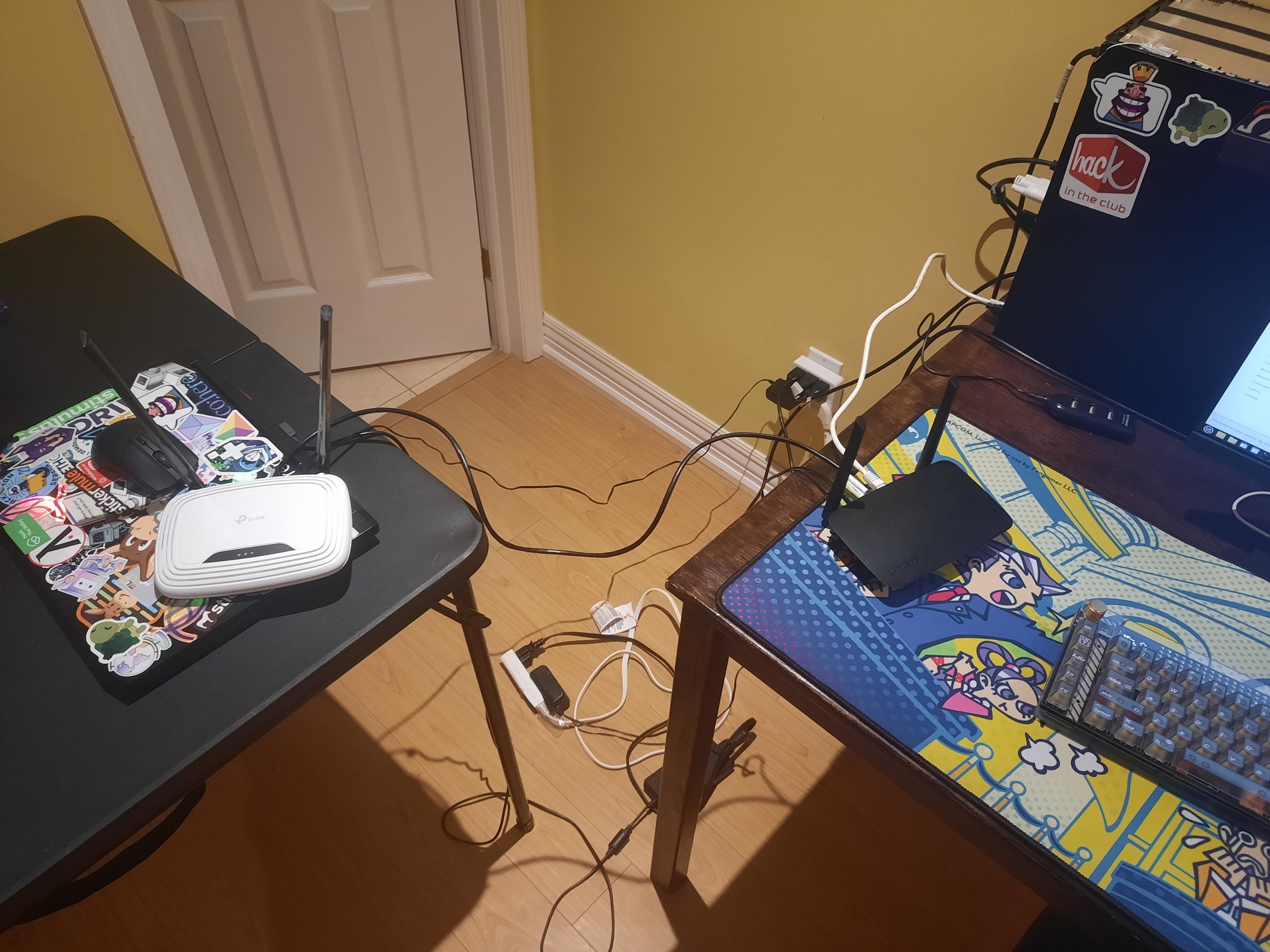
The password is the one you set in Step 7. You could also, as shown in a setup below, use another router (mine is in WIPS mode) and connect it to the E5400’s “Internet” Ethernet port.

Then you could just wget the image. This is useful as it can allow you to install LuCI without first connecting to Wifi.
Once the file is on the router, run
sysupgrade <IMAGENAME>
After some logs your router will boot into the latest version of OpenWRT available. Run passwd again to set the root password and enjoy!